Selection of Current transformer for accurate measurement and reliable protection scheme
Selection of Current transformer
In Power system it is necessary to measure current but it is not feasible to measure current directly with measuring devise as higher current can damage the measuring devise or relay. So Current transformer is required that reduce current in measuring circuit (secondary) proportional to flowing current. Current transformer isused for metering and protection purpose.
Selection of CTs In industrial Applications should be done properly for accurate measurement and reliable protection scheme so selection of CT plays significant role for metering and designing protection system. Various factors need to consider while selecting current transformer.
CT ratiois defined as ratio of primary and secondary current of CT. In order to defineprimary current of CT, consider subsequent rating of current to be measured or it should be selected from rating of circuit breaker. For example, if current to be measured is 340 A then Primary current rating of CT shall be 400 A. For secondary current, there are two standard values, 1 A and 5 A which are decided by distance between CT and measuring instrument/relay. 5A current to be considered if distance between CT and measuring instrument/relay is less. Generally we consider 5A secondary current when CT and measuring instrument/relay are in same switchboard. 1A current shall be considered if distance between CT and measuring instrument/relay is more. Power loss shall be high in case of long distance. For Instance, If CT to be installed for measuring 340A and meter is within same switchboard then CT ratio shall be stated as 400/5A.
Burden is termed as load on secondary circuit of current transformer so it is measured in VA. It can be expressed as a product ofsecondary current and total impedance of secondary circuit. Total impedance is sum of CT secondary winding impedance, impedance of connecting wire and impedance of measuring instrument/relay. If secondary current is 5 A than burden will 25 times higher than burden of 1 A CT, So it is advisable to select 1 A secondary current if distance between Ct and Instrument is more. Value of burden should be selected as close as possible to total impedance but higher than calculated total impedance otherwise it affects accuracy of measurement. Standard rated burden are 2.5 VA, 5 VA, 7.5 VA, 10 VA, 15 VA and 20 VA for Low voltage CT.
Accuracy class states the precision level of measurement. Standard value of accuracy class is 0.1, 0.2, 0.5, 1, 1.5, PS, 5P and 10P.
0.1 accuracy class means 0.1% error is acceptable in measurement. For metering purpose class 0.1 to 1.5 CT is considered to achieve higher accuracy at rated current.
5P and 10P class are considered for protection purpose only where P stands for protection purpose and PS class is special class used for differential and REF protection which required higher accuracy.
Instrument safety factor (ISF)of current transformer is ratio of limit primary current to rated primary current. If current increases more than limit primary current then core of CT shall be saturate and protect metering equipment in overcurrent condition. For example if core of CT with 800/5A ratio gets saturated at 4000A then its ISF is 5. ISF is defined only for measuring CT as protection class CTs are intended to flow fault current through measuring/Protecting devices.
Accuracy class factor isratio of nominal overcurrent to be measured to primary rated current. This factor is defined only for protection CT. The function of protection CT is to measure current in fault condition so its core should not get saturated in fault condition. ACF is placed after accuracy class designation in percentage. To illustrate, 5P10 class means that 10 times over current than primary rated current causes not more than 5% error in measurement of primary current.
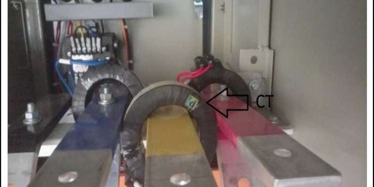
CTs are also classified in terms of construction; wound type and window type CT. It is preferable to use wound type CT in case of low primary current and window type CT are selected if primary current is high. In window type CT, primary conductor is cable or busbar passing through CT and it is not advisable to use for measuring low current as its accuracy reduce. Finally CT shall be selected depending upon size of cable or busbar. In high voltage application, CT with multiple secondary winding can be used means separate winding for metering and protection in single CT.
In VMS, Process for Selection of CTs is being done considering all aspects and we provide technical specification of CT as per IS-2705 and IEC-61869. We consider protection CT in HT panel and incomers of Main LT panel and metering CT in all feeders of Main LT panel, incomer of other panel and feeder for machines as per project requirement.
Call project management services in India at +91 – 79 – 40236 236, Email at [email protected]
Website - https://www.vmsconsultants.com/
Free Consultation - https://www.vmsconsultants.com/free-consultation/
Inquire us online - https://www.vmsconsultants.com/contact-us/